


 |
| 3/4 x 3/4 x 6 inch pieces |
 |
| Ready to apply wood glue |
 |
| Sanding, sanding and sanding and finishing |


Program (HiTec-C) #include#include __CONFIG(UNPROTECT & WDTDIS & BORDIS & MCLRDIS & PWRTDIS & WDTDIS & INTIO); #define _XTAL_FREQ 4000000 void init() { TRISIO = 0b00000001; CMCON = 0b00000111; // Comparator Off ADCON0 = 0b10000001; // Ref = Vdd, Chan = 0, AD = On ANSEL = 0b01010001; // FOSC/16 __delay_us(30); // Acquisition Delay Min 20 uSec } int read_adc() { unsigned int n; GODONE = 1; // Start conversion while(GODONE); // wait for done n = (unsigned int)ADRESH << 8 | ADRESL; return n; } void delay_ms(int n) { while (n-- > 0) __delay_ms(1); } void FlashLED(int delay, int count) { while (count-- > 0) { GPIO2 = 1; delay_ms(delay); GPIO2 = 0; delay_ms(delay); } } void main(void) { init(); GPIO1 = 0; GPIO5 = 0; FlashLED(1000, 1); while (1) { unsigned int t; int bCharging; int bReady; t = read_adc(); // Note: adjust following magic numbers according to your setup. // Battery Level High if (t > 900) { GPIO5 = 1; // stop charging bCharging = 0; } else if (t < 860) { GPIO5 = 0; // charging bCharging = 1; } // Battery Level Low if (t < 750) { bReady = 0; // battery is discharged a lot GPIO1 = 0; // disconnect the load delay_ms(30000); } else if (t > 770) { GPIO1 = 1; // battery ready for working bReady = 1; } if (bCharging == 0) // > 13v FlashLED(2000, 1); else if (bReady == 1) // > 12.3v FlashLED(200, 1); else if (bReady == 0) // < 12.3v FlashLED(25, 2); delay_ms(2000); } }
 |
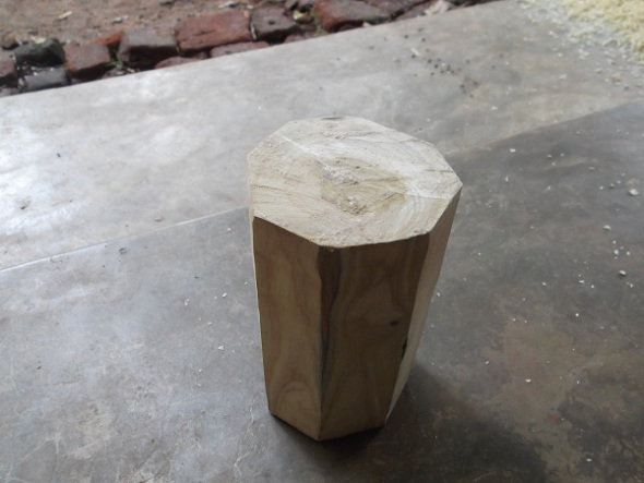
| Octagonal shape is planned using hand planner |
 |
| Drilled lot of holes on the top with a 3/8" bit. Removed rest of the material with a chisel. |


 |
| Sanded |
 |
| With first coat of varnish |


 |
| LED සහ push button එක සඳහා plug base එක හිල් කලා |
 |
#include <12F629.h>
#FUSES NOWDT //No Watch Dog Timer
#FUSES INTRC_IO //Internal RC Osc, no CLKOUT
#FUSES NOCPD //No EE protection
#FUSES NOPROTECT //Code not protected from reading
#FUSES MCLR //Master Clear pin enabled
#FUSES NOPUT //No Power Up Timer
#FUSES NOBROWNOUT //No brownout reset
#use delay(int=4000000)

#define PUSH_BTN    PIN_A0
#define SETUP_LED   PIN_A1
#define RUN_LED     PIN_A2
#define RELAY       PIN_A4
#define SPEAKER     PIN_A5
#define DEBOUNCE_DELAY   30 // ms
#define SHORT_PRESS      1
#define LONG_PRESS       2
#define RELEASE_TIME_OUT 3 // took too long to release
int16 gi_TimerDuration = 0; // The switch is kept on this amount of seconds
int16 gi_Remaining = 0; // Number of seconds remaining to switch off
//------------------------------------------------------------------------------
void PerSecond() // This gets called per second
{
    if (gi_Remaining > 0)
    {
        gi_Remaining--;

        // In each ~32 seconds, save remainder to continue automatically after a power outage
        if ((gi_Remaining & 0x1f) == 0)
        {
             write_eeprom(2, gi_Remaining & 0xff);
             write_eeprom(3, gi_Remaining >> 8);
        }

        // Toggle Running indicator at last 10s
        //if (gi_Remaining < 10)
        // output_bit(RUN_LED, gi_Remaining & 0x1);
    }
    else if (gi_Remaining == 0)
    {
        output_low(RELAY);
        output_low(RUN_LED);
    }
}
//------------------------------------------------------------------------------
int16 time = 0; // driven by timer0
#INT_TIMER0
void isr_timer0_overflow()
{
    time++;
    if (time < 3840)
       return;

    time = 0;
    PerSecond();
}
//------------------------------------------------------------------------------
void WaitForButtonPushDown()
{
    while (true)
    {
        int n;
        int i;

        while (input_state(PUSH_BTN) == 0)
            continue;

        // Some times this is sensitive to power glitches.
        // Read consecutive 5 HIGHs to verify.
        n = 0;
        for (i = 0; i < 5; ++i)
        {
             n += input_state(PUSH_BTN);
             delay_us(200);
        }

        if (n == 5) // OK. we are satisfied
            break;
    }

    delay_ms(DEBOUNCE_DELAY);
}
//------------------------------------------------------------------------------
int WaitForButtonReleaseOrTimeout()
{
    int16 t;

    // Wait till release or time out
    t = 0;
    while (input_state(PUSH_BTN) == 1)
    {
         output_high(SPEAKER);
         delay_us(300);
         output_low(SPEAKER);
         delay_us(300);

         if (t == 500) // 1500 // ~1s time out
             return RELEASE_TIME_OUT;

         t++;
    }
    delay_ms(DEBOUNCE_DELAY);

    if (t < 300) // less than half a second
        return SHORT_PRESS;
    else
        return LONG_PRESS;
}
//------------------------------------------------------------------------------
int WaitForButtonPress()
{
    WaitForButtonPushDown();
    return WaitForButtonReleaseOrTimeout();
}
//------------------------------------------------------------------------------
void DoTheJob()
{
    if (gi_TimerDuration == 0) // holiday
        return;

    // Start new service cycle
    gi_Remaining = gi_TimerDuration;
    output_high(RELAY);
    output_high(RUN_LED);
}
//------------------------------------------------------------------------------
void StopTheJob()
{
    if (gi_Remaining == 0) // already stoped
        return;

    gi_Remaining = 0;
    output_low(RELAY);
    output_low(RUN_LED);

    write_eeprom(2, 0);
    write_eeprom(3, 0);
}
//------------------------------------------------------------------------------
void RunSetup()
{
    int16 seconds;
    int16 t;
    int a;

    // Enter the setup mode
    output_high(SETUP_LED);

    // If we entered here in case of a timeout, Wait until button release
    while (input_state(PUSH_BTN) == 1)
        continue;
    delay_ms(DEBOUNCE_DELAY);

    // Wait for a short press to start reading the duration input from user
    a = WaitForButtonPress();
    if (a == LONG_PRESS || a == RELEASE_TIME_OUT)
    {
        // Exit setup mode
        output_low(SETUP_LED);

        // Wait until release in case of a timeout
        while (input_state(PUSH_BTN) == 1)
            continue;
        delay_ms(DEBOUNCE_DELAY);

        return;
    }

    // Short press.
    // Read user input in seconds (i.e. time till next push down)
    seconds = 0;
    t = 0;
    while (input_state(PUSH_BTN) == 0)
    {
        delay_ms(7);// 10
        t++;
        output_bit(SETUP_LED, t > 90 ? 1 : 0);

        if (t == 100) // 1s
        {
            t = 0;
            seconds++;
        }
    }
    delay_ms(DEBOUNCE_DELAY);

    output_high(SETUP_LED); // as this LED is used above for 1Hz blink

    // Wait for a press to complete reading the duration input from user
    a = WaitForButtonReleaseOrTimeout();
    if (a == LONG_PRESS || a == RELEASE_TIME_OUT) // input in minutes
        gi_TimerDuration = seconds * 60; // Read minutes in seconds
    else if (a == SHORT_PRESS) // input is in seconds
        gi_TimerDuration = seconds;

    write_eeprom(0, gi_TimerDuration & 0xff);
    write_eeprom(1, gi_TimerDuration >> 8);

    // Exit setup mode.
    output_low(SETUP_LED);
    // Wait until release
    while (input_state(PUSH_BTN) == 1)
        continue;
    delay_ms(DEBOUNCE_DELAY);
}
//------------------------------------------------------------------------------
void main()
{
    int switch_mode; // Regular or Timer

    setup_timer_0(RTCC_INTERNAL | RTCC_DIV_1);

    output_high(RUN_LED);
    output_high(SETUP_LED);
    delay_ms(100);

    output_low(RELAY);
    output_low(RUN_LED);
    output_low(SETUP_LED);
    delay_ms(1000); // env stabilization

    // EEPROM
    // Byte [0,1] -> gi_TimerDuration
    // Byte [2,3] -> gi_Remaining
    // Byte [4] -> switch_mode. 1=Regular Switch, else=Timer Switch

    switch_mode = read_eeprom(4);

    // This is to switch between Regular and Timer modes. Hold down the button
    // when micro is powered on.
    if (input_state(PUSH_BTN) == 1)
    {
        // Wait until release
        while (input_state(PUSH_BTN) == 1)
        {
             output_high(SPEAKER);
             delay_us(300);
             output_low(SPEAKER);
             delay_us(300);
        }
        delay_ms(DEBOUNCE_DELAY);

        // user wants to toggle the switch mode
        if (switch_mode == 0)
            switch_mode = 1;
        else
            switch_mode = 0;

        write_eeprom(4, switch_mode);
    }

    if (switch_mode == 1)
    {
        // Regular switch

        output_high(RELAY);
        output_high(RUN_LED);

        while (TRUE)
            continue;
    }

    // Starting Timer mode.

    // Read saved configurations
    gi_TimerDuration = read_eeprom(1);
    gi_TimerDuration = gi_TimerDuration << 8 | read_eeprom(0);
    gi_Remaining = read_eeprom(3);
    gi_Remaining = gi_Remaining << 8 | read_eeprom(2);

    // Continuity after power outage.
    // Note: we save this in each 32s. so there can be a error of 32s.
    if (gi_Remaining >= 32) // not going to continue remainders of less than 32s
    {
        // little compensation (error / 2) may be preferred.
        gi_Remaining -= 16;
        output_high(RELAY);
    }
    else
        gi_Remaining = 0;

    enable_interrupts(GLOBAL);
    enable_interrupts(INT_TIMER0);

    while (TRUE)
    {
        int a;
        a = WaitForButtonPress();
        if (a == SHORT_PRESS)
        {
            if (gi_Remaining > 0)
                StopTheJob();
            else
                DoTheJob();
        }
        else if (a == LONG_PRESS || a == RELEASE_TIME_OUT)
        {
            RunSetup();
        }
    }
}
//------------------------------------------------------------------------------


 |
| පරණ CD ROM drive එකකින් තමයි පෑන උස් පහත් කරන්නේ. |

 |
| මොටරේ පොටට සම්බන්ධ කරලා තියෙන්නෙ රබර් බට කෑල්ලකින්. |


